Understanding Instrument Transformers: Types, Construction, and Working Principles
Instrument transformers play a vital role in power systems by enabling accurate measurement and protection. They allow instruments and relays to operate safely and reliably without being exposed to high voltages or currents. As power networks grow more complex, the need for precise monitoring becomes even more important. This article covers instrument transformers’ types, construction, operation, applications, and importance in the electrical industry.
What Are Instrument Transformers?
An instrument transformer is a type of transformer designed specifically for measuring electrical parameters and protecting systems. It reduces high voltages or currents to measurable levels so that standard instruments can safely monitor them. These transformers are essential in both high-voltage and low-voltage networks.
Instrument transformers serve both measurement and safety purposes, unlike power transformers that transmit energy. They isolate instruments from high-energy circuits, improving protection and accuracy.
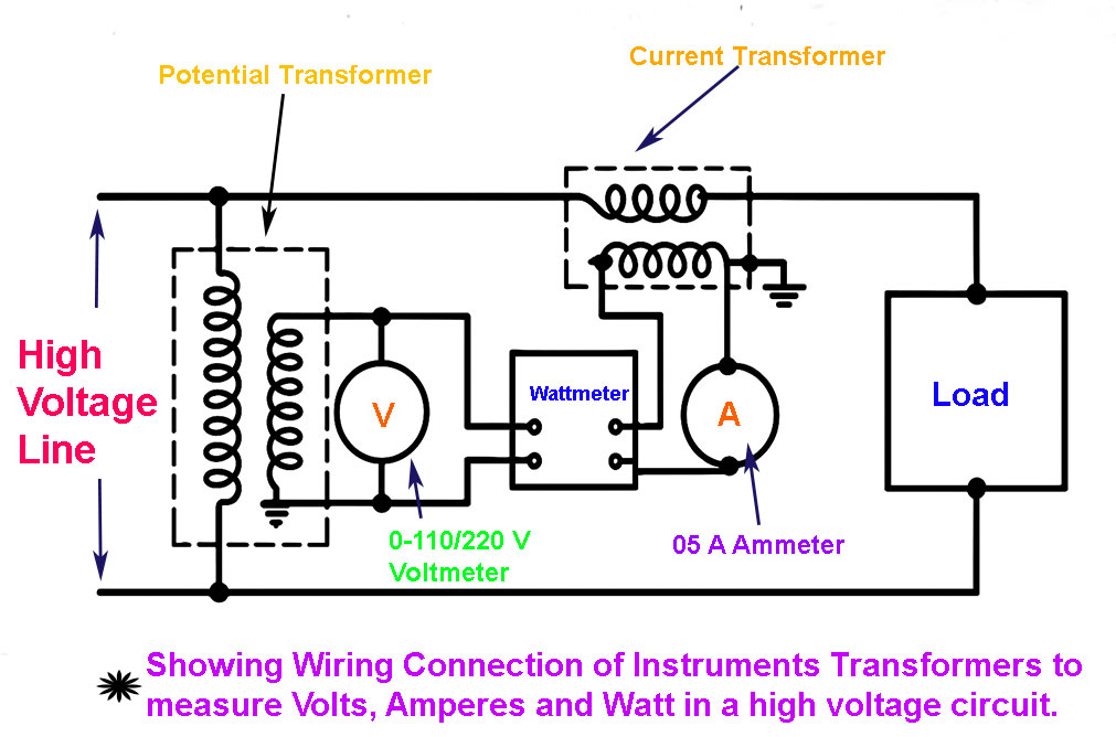
This diagram shows how instrument transformers are used to measure voltage (volts), current (amperes), and power (watts) in a high-voltage electrical circuit safely and accurately. The thick black lines at the top and bottom represent the high-voltage transmission line. Measuring directly from this line would be dangerous and inaccurate, so instrument transformers are used.
On the left side of the diagram is the potential transformer (PT). Its purpose is to step down the high voltage to a lower, measurable level, typically 110V or 220V. It is connected to a voltmeter, which measures the output voltage range of 0–110/220V. The PT is connected in parallel with the high-voltage line.
In the top center-right of the diagram is the current transformer (CT). Its function is to step down high current to a lower, safe value. It is connected to an ammeter and a wattmeter. The output current range is typically around 0–5 A, as labeled on the ammeter. The CT is connected in series with the high-voltage line going to the load.
Between the potential and current transformer circuits is the wattmeter. It measures real power (watts) consumed by the load. The wattmeter has one input from the PT for voltage and another input from the CT for current. Using these inputs, it calculates power using the formula: power (W) = voltage × current × power factor (cos φ).
The voltmeter measures voltage from the PT. The ammeter measures current from the CT. The wattmeter uses both voltage and current inputs to determine power consumption. The load, located at the far right of the diagram, represents the electrical device or system that consumes power. It receives the actual high voltage and current, while the instruments measure scaled-down signals from the PT and CT.
Why Use Instrument Transformers?
- Safety: They isolate meters and relays from high-voltage systems.
- Accuracy: They ensure precise readings even at high voltages and currents.
- Standardization: They convert large values into standard measurable ranges.
Types of Instrument Transformers
There are two primary categories of instrument transformers: current transformers (CTs) and voltage transformers (VTs). Each serves a distinct purpose in power system monitoring.
Current Transformers (CTs)
Current transformers measure the current flowing in a power circuit. They step down high current levels to safer values that measuring instruments can handle. CTs are widely used in protective relays, power meters, and energy monitoring systems.
Key Components of a CT:
- Primary Winding: A single turn or conductor connected in series with the power line.
- Secondary Winding: Multiple turns connected to a measurement device.
- Magnetic Core: Usually made of silicon steel for high permeability.
Working Principle:
When current flows through the primary winding, it creates a magnetic flux in the core. This flux induces a current in the secondary wind that is proportional to the primary current. Since the transformer steps down the current, it allows safe monitoring and control.
Applications:
- Power flow monitoring
- Fault detection and protection
- Energy management systems
Voltage Transformers (VTs) or Potential Transformers (PTs)
We use voltage transformers to reduce high voltages to measurable values. Also known as potential transformers, they allow voltmeters and protective devices to measure voltage without direct exposure.
Key Components of a VT:
- Primary Coil: Connected across the high-voltage side.
- Secondary Coil: Delivers lower voltage to the instruments.
- Insulation: Ensures safe operation at high voltages.
Working Principle:
VTs work on the same electromagnetic induction principle as other transformers. The voltage ratio between primary and secondary coils determines the scaling. The output remains proportional and precise under varying load conditions.
Applications:
- Voltage measurement
- Over voltage protection
- Synchronizing generators
The construction of Instrument Transformers
The design and construction of an instrument transformer influence its performance, accuracy, and reliability. Both CTs and VTs share similar construction aspects but differ in coil arrangements and core designs.
Core Material
High-grade silicon steel is commonly used to minimize core losses and improve magnetic flux. Some advanced designs use nano crystalline or amorphous materials for better performance.
Windings
- CT Windings: The primary winding is often a thick conductor; the secondary has many turns.
- VT Windings: Both primary and secondary have multiple turns with insulation layers.
Insulation
Insulation ensures the safety of the internal components. Depending on the application requirements, we use either oil-immersed insulation or cast resin types.
Housing and enclosures
Outdoor transformers require weatherproof and UV-resistant enclosures. Indoor types use metal or plastic casings with built-in terminals.
Mountings and Terminals
You can mount CTs and VTs on poles, panels, or substations, depending on their intended use. They come with standardized terminal blocks for easy connections.
The workings of Instrument Transformers
Instrument transformers operate using electromagnetic induction. Their function depends on Faraday’s law, which states that a change in magnetic field induces voltage.
How a CT Works:
- The primary conductor carries high current.
- A magnetic field forms around the core.
- This field induces current in the secondary winding.
- The secondary current is proportional to the primary but scaled down.
How a VT Works:
- The primary winding receives high voltage.
- Magnetic flux flows through the core.
- • The secondary winding receives scaled-down voltage.
- Instruments linked to the secondary oversee the voltage of the system.
Both types ensure electrical quantities remain within readable limits while maintaining accuracy.
Key Differences Between CT and VT
Feature Current Transformer Voltage Transformer Purpose Measures current Measures voltage Connection In series In parallel Output Current Voltage Safety Role This function safeguards meters from excessive current levels. Isolates from high voltage Typical Use Relays, ammeters Voltmeters, synchronizers
Applications of Instrument Transformers
Instrument transformers serve various roles in power systems. Some key applications include:
- Protection: They trigger circuit breakers during faults.
- Metering: They allow accurate billing and load monitoring.
- Monitoring helps analyse power quality and network health.
- Automation: They support SCADA and smart grid functions.
Industrial and Commercial Use
Factories use instrument transformers to monitor machinery load. Commercial buildings rely on them for efficient energy use and fault isolation.
Utility and Grid-Level Use
Utilities use these transformers for grid stability, energy audits, and real-time decision-making.
Benefits of Using Instrument Transformers
- Enhanced Safety: Isolate measurement devices from live circuits.
- Cost Savings: Allow standardized instruments to have multiple voltage levels.
- Improved Accuracy: Deliver consistent readings across various load conditions.
- Space Efficiency: Compact designs fit into modern installations.
Selection Criteria for Instrument Transformers
Choosing the right instrument transformer depends on several factors:
- Voltage and Current Ratings: Match with system requirements.
- Accuracy Class: Use higher classes for metering applications and moderate classes for protection applications.
- Burden Rating: Total load that the secondary can handle.
- Insulation Type: Depends on indoor or outdoor usage.
- Mounting Type: Panel, rack, or pole-mounted.
Comparison Table: Current Transformer (CT) vs Potential Transformer (PT)
| Aspect | Current Transformer (CT) | Potential Transformer (PT) |
|---|---|---|
| Primary Function | Measures high current by stepping it down to a lower, measurable value | Measures high voltage by stepping it down to a safe, measurable level |
| Input Type | High current (typically in amperes) | High voltage (typically in kilovolts) |
| Output Type | Proportional low current (e.g., 5A or 1A) | Proportional low voltage (e.g., 110V or 63.5V) |
| Construction | Typically has a few turns on the primary and many on the secondary | Usually has many turns on both primary and secondary windings |
| Installation | Installed in series with the line | Installed in parallel with the line |
| Burden (Load) Rating | Expressed in VA and affects accuracy | Also rated in VA; accuracy affected by burden and voltage load |
| Accuracy Class | Depends on use (e.g., metering vs protection) | Also has various classes for different applications |
| Typical Ratio | e.g., 1000:5, 500:5 | e.g., 11kV:110V, 132kV:110V |
| Use Case in Power Systems | Used to measure current and operate protection relays | Used to measure voltage and supply inputs to meters/relays |
| Safety Considerations | Secondary must never be open-circuited when energized | Safer to open-circuit but should still be avoided |
| Cost | Generally less expensive than PTs | More costly due to insulation requirements and construction |
| Phase Shift | Minor, can affect metering accuracy | Generally low, but must be considered in high-precision metering |
| Applications | Energy meters, protection relays, fault analysis | Voltage monitoring, metering, control systems |
Frequently Asked Questions
Q1. Why are instrument transformers important in power systems?
They ensure accurate measurement and system protection while isolating equipment from dangerous voltages and currents.
Q2. How does a current transformer differ from a power transformer?
A current transformer measures current and has a different design and function from a power transformer, which transmits energy.
Q3. Can residential systems use instrument transformers?
Although compact models are more commonly found in industrial and utility setups, they also exist for residential solar or monitoring systems.
Q4. How are these transformers maintained?
Periodic testing, insulation checks, and ensuring terminal tightness are part of regular maintenance.
Q5. Are digital instrument transformers available?
Yes. Digital models integrate with smart meters and SCADA systems, offering better accuracy and real-time data.
Conclusion
Instrument transformers are foundational elements in modern electrical systems. Whether it’s a current or voltage transformer, these devices help manage, protect, and optimize power flow across grids and installations. By stepping down high values and enabling precise monitoring, they enhance both safety and efficiency. Understanding their types, construction, and functionality empowers engineers and technicians to make informed decisions that drive smarter and safer power systems.
Throughout this article, we explored how an instrument transformer works, the importance of choosing the right one, and how these critical instruments support today’s evolving electrical infrastructure.
