Understanding electrical systems requires a firm grasp of the tools used to measure and manage voltage and current. Among these, instrument transformers play a crucial role in ensuring accurate readings and safe operations. A potential transformer is one such specialized device, used primarily to measure high voltages in power systems. Unlike current transformers that deal with current, potential transformers focus exclusively on voltage. These transformers help scale down high voltages to safer, measurable levels suitable for instruments and relays.
What Are Instrument Transformers?
Instrument transformers are essential devices used in electrical power systems to facilitate the measurement and monitoring of high voltages and currents. They provide a scaled-down representation of the actual electrical quantities, allowing for safe and accurate analysis. The two main categories include:
- Current Transformers (CTs)
- Potential Transformers (PTs)
Importance of Instrument Transformers
Instrument transformers, including potential transformers, ensure:
- Enhanced safety for personnel and measuring instruments.
- Accurate monitoring and recording of electrical values.
- Efficient relay operation for protective functions.
What Is a Potential Transformer?
A potential transformer is a voltage step-down device used to convert high-voltage levels to standardized low-voltage outputs. These outputs are compatible with measuring instruments and protective relays. PTs maintain the frequency and phase of the original voltage signal, ensuring high fidelity in voltage measurement.
Role in Power Systems
In modern power systems, a potential transformer ensures that high-voltage circuits can be measured safely. The reduced voltage output helps in:
- Energy metering
- Voltage regulation
- System protection
- Synchronization of generators
By transforming high potential levels into safer, lower voltages, PTs make system monitoring feasible and secure.
Importance of Potential Transformers in Power Systems
The contribution of potential transformers to power systems is significant. They serve as the backbone for numerous functions:
- Accurate Metering: Essential for billing and energy audits.
- System Protection: Triggers protective relays during faults.
- Voltage Regulation: Maintains voltage within prescribed limits.
- Data Logging: Supports historical trend analysis.
The transformer must deliver these benefits without introducing significant errors, underscoring the need for quality construction and regular calibration.
Types of Potential Transformers
Different PT designs cater to various electrical environments and measurement requirements. Below are the common types:
1. Electromagnetic Potential Transformers
These operate based on Faraday’s Law of Electromagnetic Induction. The construction involves a laminated magnetic core around which primary and secondary windings are placed.
Advantages:
- High accuracy
- Cost-effectiveness
- Long operational life
- Simple design
Limitations:
- Limited to moderate voltage applications.
- Bulky for very high voltages.
2. Capacitive Potential Transformers (CVTs)
These use a capacitive voltage divider along with an intermediate transformer to step down voltages. They are typically employed in systems exceeding 100 kV.
Components:
- Series-connected capacitors.
- Inductive voltage transformer.
- Compensation reactor.
Benefits:
- Lightweight and compact.
- Economical at high voltages.
- Suitable for remote voltage monitoring.
3. Optical Potential Transformers
Also called optical voltage transformers (OVTs), they use fiber optics and electro-optic materials to measure voltage. Their high-end technology makes them suitable for advanced applications.
Key Features:
- Immune to electromagnetic interference.
- Compact and lightweight.
- Ideal for digital substations and high-speed monitoring.
Downsides:
- High cost
- Requires specialized installation

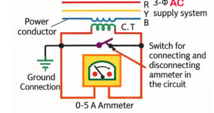
This above image illustrates the working principle of a potential transformer in an electrical circuit. A potential transformer, also known as a voltage transformer, is used to step down high voltages to lower, measurable levels for instruments and protective relays in power systems. In the diagram, the high-voltage AC supply is applied to the primary winding of the potential transformer. This primary winding consists of a large number of turns and is connected in parallel with the power line whose voltage needs to be measured.
A fuse is placed in series with the primary winding to provide protection against overcurrents and short circuits. This ensures that the system remains safe in case of faults. The primary winding is magnetically coupled to the secondary winding, which contains a smaller number of turns. The purpose of having fewer turns in the secondary is to produce a lower voltage that is proportional to the high voltage in the primary.
This stepped-down voltage in the secondary is then fed into a voltmeter, which is calibrated to reflect the original high voltage based on the known transformation ratio of the potential transformer. The voltmeter is grounded for safety to protect both the equipment and personnel from accidental electric shocks. The load connected to the high-voltage supply continues to operate normally while the potential transformer allows for safe voltage measurement without direct connection to the high-voltage line.
The entire setup ensures accuracy in measurement and isolation of measuring instruments from high-voltage circuits, thereby maintaining the integrity and safety of the system.
Construction of a Potential Transformer
A potential transformer typically includes several major components, each contributing to its function and reliability.
Core
The core is generally made from laminated silicon steel. This design minimizes eddy current losses, thereby increasing efficiency and reducing heat generation.
Windings
- Primary Winding: Receives the high-voltage input from the system.
- Secondary Winding: Outputs a low, proportional voltage for metering or protective devices.
The windings are meticulously insulated and positioned to avoid breakdown and interference.
Insulation System
Insulation materials vary depending on the application. For high-voltage PTs:
- Oil-impregnated paper
- Epoxy resin
- SF6 gas
These materials provide both electrical insulation and mechanical stability.
Enclosure
PTs are housed in sealed, grounded metal or polymeric enclosures. These casings:
- Prevent external contamination
- Offer protection against weather and mechanical damage
- Ensure operator safety
Working Principle of Potential Transformers
The working principle of a potential transformer revolves around electromagnetic induction:
- The high-voltage AC signal is fed into the primary winding.
- A magnetic flux is generated in the laminated core.
- This magnetic field induces a voltage in the secondary winding.
- The secondary voltage is directly proportional to the primary voltage.
- Measuring instruments connected to the secondary winding receive a scaled, safe voltage for further processing.
This process ensures that the potential being measured reflects the actual conditions of the power system.
Accuracy Classes and Standards
The performance of a PT is defined by its accuracy class, as outlined in standards like IEC and ANSI.
Common Accuracy Classes:
- 0.1, 0.2, 0.5, 1.0: Suitable for metering
- 3P, 6P: Suitable for protection
These classes indicate the maximum error allowed at rated conditions.
Key Specifications of Potential Transformers
When selecting a potential transformer, you must consider several critical parameters:
| Parameter | Description |
|---|---|
| Primary Voltage | The high voltage side of the system |
| Secondary Voltage | Usually 110V or 120V for compatibility |
| Accuracy Class | Indicates measurement precision |
| Frequency | Typically 50 Hz or 60 Hz |
| Burden | Load on the secondary circuit |
These values help ensure the PT matches the system’s requirements and delivers accurate results.
Installation and Maintenance Tips
Proper handling of a potential transformer starts with installation and continues with periodic maintenance.
Installation Guidelines:
- Maintain vertical orientation for oil-immersed PTs.
- Use specified mounting brackets.
- Ensure adequate ventilation.
- Verify polarity markings.
Maintenance Best Practices:
- Conduct insulation resistance tests.
- Check oil level (if applicable).
- Clean terminals and bushings.
- Test accuracy using a known reference.
Scheduled maintenance improves reliability and extends the service life of the transformer.
Applications of Potential Transformers
PTs are used in a broad range of industries, including:
Electrical Utilities
- Metering of transmission and distribution lines.
- Monitoring substation voltages.
Industrial Facilities
- Power monitoring in manufacturing plants.
- Automation systems requiring voltage feedback.
Renewable Energy Systems
- Voltage regulation in wind and solar power stations.
- Integration with grid systems.
Research and Education
- Laboratory voltage monitoring.
- Student training modules.
Each of these applications underscores the potential of PTs to contribute to efficient, safe, and intelligent power systems.
Benefits of Using Potential Transformers
Employing potential transformers provides numerous advantages:
- Safety: Isolates measuring instruments from high-voltage lines.
- Accuracy: Maintains measurement consistency.
- Reliability: Offers long service life under rigorous conditions.
- Ease of Use: Integrates seamlessly with standard instruments.
- Cost Efficiency: Reduces damage and maintenance on sensitive devices.
By stepping down the potential to a usable range, these transformers minimize the risks associated with direct voltage measurement.
Limitations and Challenges
Despite their many benefits, potential transformers do present some challenges:
- Sensitivity to Load: Overloading the secondary can distort readings.
- Environmental Stress: Moisture and dust can impair insulation.
- Accuracy Drift: Can occur due to aging or thermal cycling.
- Size and Weight: Especially in older or oil-filled models.
Addressing these issues through modern materials and digital calibration tools can greatly enhance their longevity and precision.
Comparison: Potential Transformers vs Current Transformers
| Feature | Potential Transformer | Current Transformer |
|---|---|---|
| Measures | Voltage | Current |
| Connection | Parallel | Series |
| Output | Proportional low voltage | Proportional low current |
| Safety Function | Voltage isolation | Current isolation |
| Accuracy Class | 0.1 to 1.0 for metering | 0.1 to 5P for protection |
Both types of instrument transformers work in harmony to enable comprehensive monitoring of power systems.
Frequently Asked Questions (FAQs)
Q1: Why is a potential transformer crucial in high-voltage systems?
A: It enables safe voltage measurement and effective relay operations by stepping down high voltages.
Q2: How do you maintain the accuracy of a PT?
A: Regular testing, proper installation, and adherence to rated burden help maintain precision.
Q3: What safety measures should be taken during PT installation?
A: Always ensure grounding, use personal protective equipment, and follow electrical codes.
Q4: Can PTs be used in combination with CTs?
A: Yes. PTs and CTs together provide full-spectrum electrical monitoring.
Q5: Are there digital alternatives to traditional PTs?
A: Yes. Optical and digital PTs offer advanced features like remote diagnostics and real-time data output.
Conclusion
A potential transformer is a vital component in any electrical system where voltage measurement and protection are necessary. With their ability to reduce high voltages to manageable levels while maintaining accuracy and isolation, PTs ensure that systems run safely and efficiently. Their importance spans across sectors, from utilities to industrial automation. By understanding their types, construction, and applications, professionals can make informed decisions that enhance system reliability and performance. Harnessing the full potential of these devices unlocks smarter, safer, and more effective power management solutions.